+91 - 77698 27676
+91 - 77698 27676
| Output Power W | Model | Frequency Hz | Supply Voltage Volt | Current A | Starting Torque Kg.cm | Rated Torque Kg. cm |
Rated Speed RPM | Capacitor |
25 |
80 4G IW 25 |
60 |
110 V Single Phase |
0.40 |
1.2 |
1.7 |
1450 |
2.5 |
25 |
80 4G IX 25 |
50 |
230 V Single Phase |
0.20 |
1.2 |
1.8 |
1250 |
1.5 |
25 |
80 4G IY 25 |
60 |
230 V Three Phase |
0.21 |
2.0 |
1.7 |
1450 |
----- |
25 |
80 4G IY 25 |
50 |
230 V Three Phase |
0.20 |
1.9 |
1.6 |
1350 |
----- |
25 |
80 4G IZ 25 |
50 |
415 V Three Phase |
0.15 |
1.5 |
1.7 |
1350 |
----- |
The maximum permissible torque is 80 kg. cm
RPM |
500 |
416 |
300 |
250 |
200 |
166 |
120 |
100 |
83 |
60 |
50 |
41 |
30 |
25 |
20 |
16 |
15 |
12.5 |
10 |
8.3 |
Gear Ratio |
3 |
3.6 |
5 |
6 |
7.5 |
9 |
12.5 |
15 |
18 |
25 |
30 |
36 |
50 |
60 |
75 |
90 |
100 |
120 |
150 |
180 |
Output Torque |
5 |
6 |
8.3 |
10 |
12 |
15 |
21 |
25 |
30 |
41 |
48 |
58 |
72 |
80 |
80 |
80 |
80 |
80 |
80 |
80 |
RPM |
600 |
500 |
360 |
300 |
240 |
200 |
144 |
120 |
100 |
72 |
60 |
50 |
36 |
30 |
24 |
20 |
18 |
15 |
12 |
10 |
Gear Ratio |
3 |
3.6 |
5 |
6 |
7.5 |
9 |
12.5 |
15 |
18 |
25 |
30 |
36 |
50 |
60 |
75 |
90 |
100 |
120 |
150 |
180 |
Output Torque |
4 |
5 |
7 |
8.3 |
10 |
12 |
17 |
22 |
25 |
31 |
37 |
45 |
56 |
68 |
80 |
80 |
80 |
80 |
80 |
80 |
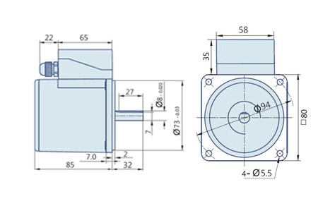
Gear Boxes are sold separately.
A Sky blue colored background indicates gear shaft rotation in the same direction; a Brown background indicates rotation in the opposite direction as the motor shaft. The speed of the Gear Motor is calculated by dividing the motor's synchronous speed (50 Hz; 1500 RPM & 60 Hz; 1800 RPM) by the ratio.
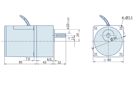
The actual speed is 2~20% less than the displayed value, depending upon the load size. Characteristics, specifications and dimensions are subjected to change without prior notice.
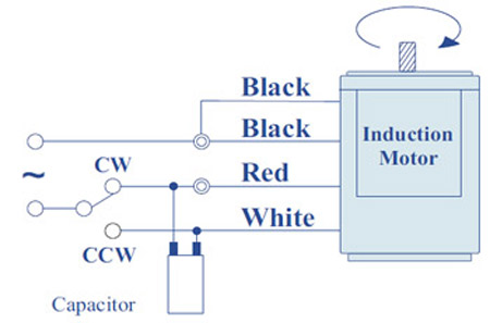
Short the Black wires and connect as shown in fig., To rotate the motor in Clockwise direction. To change the direction, flip CW to CCW.
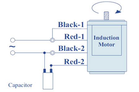
Black Wires are for Starting purpose and Red wires for the Running purpose, as shown in fig., To change the direction, interchange Black wires or Red wires
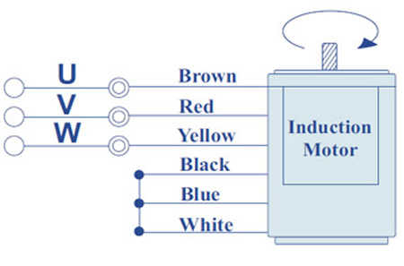
For the Voltage 415 VAC, 3-Phase Supply, Wires are connected as shown in the fig. Short Blue, Black and White and then insulate it carefully. To change the direction, interchange any two wires between U, V & W.
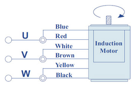
For the Voltage 230 VAC, 3-Phase Supply, Wires are connected as shown in the fig. Short Blue & Red, Black & Yellow, and White& Red as per the fig. Shown. To change the direction, interchange any two wires between U, V & W.
Change the direction of the motor only after it stops rotating, if the attempt is made during rotation, the motor may ignore the reversing command or change the direction after some time.
© Revolution Technology All rights reserved.