+91 - 77698 27676
+91 - 77698 27676
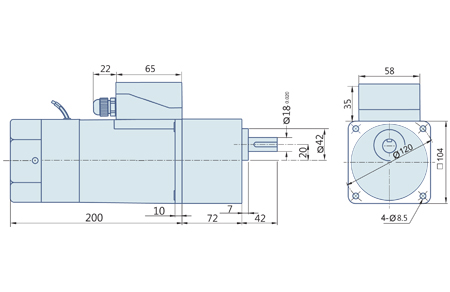
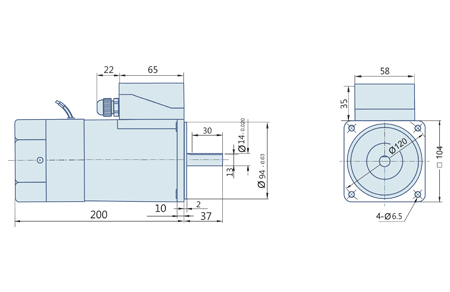
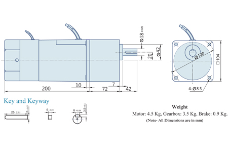
Continuous Rating with Frequent Start Stop. Load Holding & Minimum Overrun. Works when Power Off ( Brake - Activated ), By its Failsafe Braking Action. Fitted at the Back side Of the Motor. Rotates in Clockwise or Counter Clockwise Direction. Terminal box or Flying Lead Wires for Connections.
Output Power W |
Model |
Frequency Hz |
Supply Voltage Volt |
Current A |
Starting Torque Kg.cm |
Rated Torque Kg. cm |
Rated Speed RPM |
Capacitor |
200 |
104 4G IW 200 |
60 |
110 V Single Phase |
3.2 |
16 |
18 |
1500 |
18 |
200 |
104 4G IX 200 |
50 |
230 V Single Phase |
1.2 |
15 |
18 |
1350 |
5 |
The maximum permissible torque is 200 kg. cm
| 50Hz Unit : kg.cm | ||||||||||||||||||||
RPM |
500 |
416 |
300 |
250 |
200 |
166 |
120 |
100 |
83 |
60 |
50 |
41 |
30 |
25 |
20 |
16 |
15 |
12.5 |
10 |
8.3 |
Gear Ratio |
3 |
3.6 |
5 |
6 |
7.5 |
9 |
12.5 |
15 |
18 |
25 |
30 |
36 |
50 |
60 |
75 |
90 |
100 |
120 |
150 |
180 |
Output Torque |
41 |
49 |
68 |
81 |
103 |
123 |
163 |
196 |
235 |
330 |
392 |
400 |
400 |
400 |
400 |
400 |
400 |
400 |
400 |
400 |
| 60Hz Unit : kg.cm | ||||||||||||||||||||
RPM |
600 |
500 |
360 |
300 |
240 |
200 |
144 |
120 |
100 |
72 |
60 |
50 |
36 |
30 |
24 |
20 |
18 |
15 |
12 |
10 |
Gear Ratio |
3 |
3.6 |
5 |
6 |
7.5 |
9 |
12.5 |
15 |
18 |
25 |
30 |
36 |
50 |
60 |
75 |
90 |
100 |
120 |
150 |
180 |
Output Torque |
34 |
41 |
57 |
69 |
85 |
101 |
135 |
162 |
195 |
275 |
326 |
390 |
400 |
400 |
400 |
400 |
400 |
400 |
400 |
400 |
Gear Boxes are sold separately.
A Sky blue colored background indicates gear shaft rotation in the same direction; a Brown background indicates rotation in the opposite direction as the motor shaft. The speed of the Gear Motor is calculated by dividing the motor's synchronous speed ( 50 Hz; 1500 RPM & 60 Hz; 1800 RPM) by the ratio
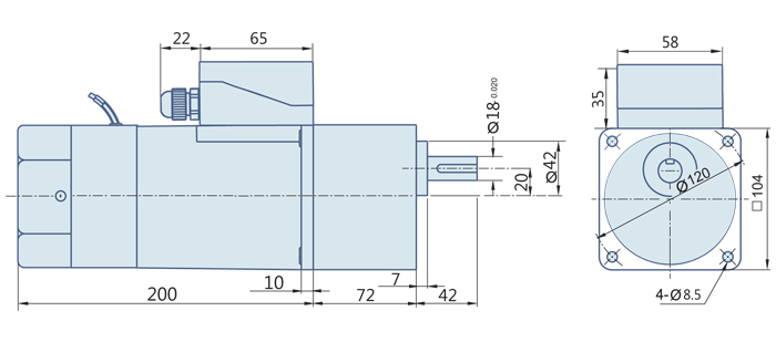
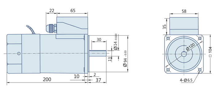
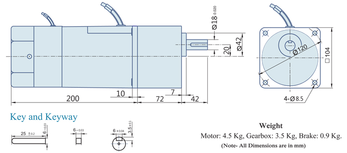
The actual speed is 2 ~ 20% less than the displayed value, depending upon the load size. Characteristics, specifications and dimensions are subjected to change without prior notice.
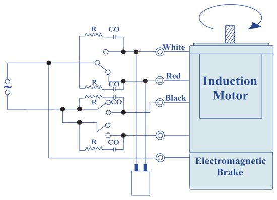
When Sw1 is switched ON, Electromagnetic Brake is released & motor starts rotating. When Sw1 is switched OFF then Electromagnetic Brake will be applied stopping the motor immediately & holding the load. Apply voltage on the blue brake lead wires only, to release the Electromagnetic Brake. To change the direction of rotation, flip Cw to CCW.
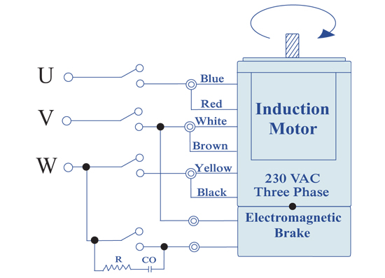
When Sw1 is switched ON, Electromagnetic Brake is released & motor starts rotating. When Sw1 is switched OFF then Electromagnetic Brake will be applied stopping the motor immediately & holding the load. Apply voltage on the blue brake lead wires only, to release the Electromagnetic Brake. To change the direction of rotation, interchange any two wires between U, V & W.
Change the direction of the motor only after it stops rotating, if the attempt is made during rotation, the motor may ignore the reversing command or change the direction after some time.
© Revolution Technology All rights reserved.